

Magnetic Field Of Straight Wire
Chapter 12. Sources of Magnetic Fields
12.ii Magnetic Field Due to a Sparse Straight Wire
Learning Objectives
By the end of this section, you will be able to:
- Explain how the Biot-Savart constabulary is used to determine the magnetic field due to a thin, straight wire.
- Determine the dependence of the magnetic field from a thin, straight wire based on the distance from it and the current flowing in the wire.
- Sketch the magnetic field created from a sparse, straight wire past using the second right-hand dominion.
How much current is needed to produce a significant magnetic field, maybe as strong as Globe's field? Surveyors volition tell you that overhead electric power lines create magnetic fields that interfere with their compass readings. Indeed, when Oersted discovered in 1820 that a current in a wire afflicted a compass needle, he was not dealing with extremely large currents. How does the shape of wires carrying current affect the shape of the magnetic field created? We noted in Affiliate 28 that a current loop created a magnetic field similar to that of a bar magnet, but what nearly a direct wire? We can apply the British indian ocean territory-Savart law to answer all of these questions, including determining the magnetic field of a long directly wire.
Figure 12.5 shows a department of an infinitely long, directly wire that carries a current I. What is the magnetic field at a point P, located a distance R from the wire?
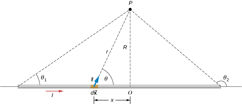
Let's begin by considering the magnetic field due to the current element [latex]I\phantom{\rule{0.2em}{0ex}}d\stackrel{\to }{\textbf{x}}[/latex] located at the position x. Using the right-hand rule 1 from the previous chapter, [latex]d\stackrel{\to }{\textbf{x}}\phantom{\rule{0.2em}{0ex}}×\phantom{\rule{0.2em}{0ex}}\hat{\textbf{r}}[/latex] points out of the folio for whatever element forth the wire. At point P, therefore, the magnetic fields due to all current elements have the aforementioned management. This means that nosotros tin calculate the internet field in that location past evaluating the scalar sum of the contributions of the elements. With [latex]|d\stackrel{\to }{\textbf{ten}}\phantom{\dominion{0.2em}{0ex}}×\phantom{\rule{0.2em}{0ex}}\hat{\textbf{r}}|=\left(dx\right)\left(1\right)\mathrm{sin}\phantom{\rule{0.1em}{0ex}}\theta ,[/latex] we have from the British indian ocean territory-Savart police force
[latex]B=\frac{{\mu }_{0}}{iv\pi }\underset{\text{wire}}{\int }\frac{I\mathrm{sin}\phantom{\rule{0.1em}{0ex}}\theta \phantom{\dominion{0.1em}{0ex}}dx}{{r}^{2}}.[/latex]
The wire is symmetrical nigh point O, so nosotros tin set the limits of the integration from null to infinity and double the answer, rather than integrate from negative infinity to positive infinity. Based on the flick and geometry, we can write expressions for r and [latex]\mathrm{sin}\phantom{\rule{0.1em}{0ex}}\theta[/latex] in terms of x and R, namely:
[latex]\begin{assortment}{ccc}\hfill r& =\hfill & \sqrt{{x}^{2}+{R}^{two}}\hfill \\ \hfill \mathrm{sin}\phantom{\dominion{0.1em}{0ex}}\theta & =\hfill & \frac{R}{\sqrt{{10}^{ii}+{R}^{2}}}.\hfill \end{array}[/latex]
Substituting these expressions into Equation 12.v, the magnetic field integration becomes
[latex]B=\frac{{\mu }_{o}I}{2\pi }{\int }_{0}^{\infty }\frac{R\phantom{\rule{0.2em}{0ex}}dx}{{\left({x}^{2}+{R}^{ii}\correct)}^{3\text{/}2}}.[/latex]
Evaluating the integral yields
[latex]B=\frac{{\mu }_{o}I}{two\pi R}{\left[\frac{x}{{\left({ten}^{2}+{R}^{2}\right)}^{one\text{/}2}}\correct]}_{0}^{\infty }.[/latex]
Substituting the limits gives united states of america the solution
[latex]B=\frac{{\mu }_{o}I}{two\pi R}.[/latex]
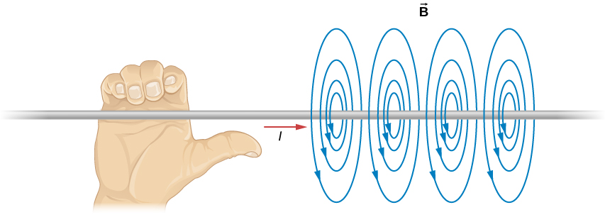
The magnetic field lines of the space wire are circular and centered at the wire (Figure 12.six), and they are identical in every aeroplane perpendicular to the wire. Since the field decreases with distance from the wire, the spacing of the field lines must increase correspondingly with distance. The direction of this magnetic field may exist institute with a second form of the correct-hand rule (illustrated in Effigy 12.6). If you hold the wire with your correct paw so that your thumb points along the electric current, so your fingers wrap around the wire in the same sense as [latex]\stackrel{\to }{\textbf{B}}.[/latex]
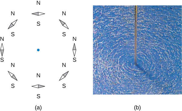
The direction of the field lines can be observed experimentally by placing several small-scale compass needles on a circle well-nigh the wire, as illustrated in Effigy 12.7. When at that place is no current in the wire, the needles align with Earth's magnetic field. However, when a big electric current is sent through the wire, the compass needles all signal tangent to the circle. Atomic number 26 filings sprinkled on a horizontal surface also delineate the field lines, as shown in Figure 12.7.
Instance
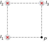
Calculating Magnetic Field Due to Three Wires
Three wires sit down at the corners of a square, all carrying currents of 2 amps into the page as shown in Figure 12.8. Calculate the magnitude of the magnetic field at the other corner of the foursquare, bespeak P, if the length of each side of the foursquare is 1 cm.
Strategy
The magnetic field due to each wire at the desired point is calculated. The diagonal distance is calculated using the Pythagorean theorem. Next, the direction of each magnetic field's contribution is determined by drawing a circle centered at the point of the wire and out toward the desired point. The direction of the magnetic field contribution from that wire is tangential to the curve. Lastly, working with these vectors, the resultant is calculated.
Solution
Prove Answer
Wires 1 and 3 both take the same magnitude of magnetic field contribution at point P:
[latex]{B}_{1}={B}_{3}=\frac{{\mu }_{o}I}{ii\pi R}=\frac{\left(4\pi \phantom{\rule{0.2em}{0ex}}×\phantom{\rule{0.2em}{0ex}}{10}^{\text{−7}}\text{T}\cdot \text{m/A}\correct)\left(2\phantom{\dominion{0.2em}{0ex}}\text{A}\right)}{2\pi \left(0.01\phantom{\rule{0.2em}{0ex}}\text{m}\right)}=four\phantom{\rule{0.2em}{0ex}}×\phantom{\rule{0.2em}{0ex}}{10}^{\text{−5}}\text{T}.[/latex]
Wire two has a longer distance and a magnetic field contribution at betoken P of:
[latex]{B}_{2}=\frac{{\mu }_{o}I}{ii\pi R}=\frac{\left(four\pi \phantom{\dominion{0.2em}{0ex}}×\phantom{\rule{0.2em}{0ex}}{ten}^{\text{−7}}\text{T}\cdot \text{m/A}\right)\left(2\phantom{\dominion{0.2em}{0ex}}\text{A}\correct)}{2\pi \left(0.01414\phantom{\rule{0.2em}{0ex}}\text{m}\right)}=3\phantom{\rule{0.2em}{0ex}}×\phantom{\dominion{0.2em}{0ex}}{x}^{\text{−5}}\text{T}.[/latex]
The vectors for each of these magnetic field contributions are shown.
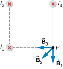
The magnetic field in the x-direction has contributions from wire iii and the x-component of wire 2:
[latex]{B}_{\text{net}\phantom{\rule{0.2em}{0ex}}10}=\text{−4}\phantom{\dominion{0.2em}{0ex}}×\phantom{\rule{0.2em}{0ex}}{10}^{\text{−v}}\text{T}-2.83\phantom{\dominion{0.2em}{0ex}}×\phantom{\rule{0.2em}{0ex}}{x}^{\text{−five}}\text{T}\phantom{\rule{0.2em}{0ex}}\mathrm{cos}\left(45\text{°}\right)=\text{−half dozen}\phantom{\rule{0.2em}{0ex}}×\phantom{\rule{0.2em}{0ex}}{ten}^{\text{−v}}\text{T}.[/latex]
The y-component is similarly the contributions from wire ane and the y-component of wire 2:
[latex]{B}_{\text{net}\phantom{\dominion{0.2em}{0ex}}y}=\text{−4}\phantom{\rule{0.2em}{0ex}}×\phantom{\rule{0.2em}{0ex}}{10}^{\text{−5}}\text{T}-2.83\phantom{\rule{0.2em}{0ex}}×\phantom{\rule{0.2em}{0ex}}{10}^{\text{−five}}\text{T}\mathrm{sin}\left(45\text{°}\correct)=\text{−half dozen}\phantom{\rule{0.2em}{0ex}}×\phantom{\rule{0.2em}{0ex}}{10}^{\text{−5}}\text{T}.[/latex]
Therefore, the internet magnetic field is the resultant of these two components:
[latex]\begin{assortment}{}\\ \\ {B}_{\text{net}}=\sqrt{{B}_{\text{net}\phantom{\dominion{0.2em}{0ex}}x}^{2}+{B}_{\text{net}\phantom{\rule{0.2em}{0ex}}y}^{2}}\\ {B}_{\text{internet}}=\sqrt{{\left(\text{−six}\phantom{\dominion{0.2em}{0ex}}×\phantom{\rule{0.2em}{0ex}}{10}^{\text{−five}}\text{T}\right)}^{ii}+{\left(\text{−vi}\phantom{\rule{0.2em}{0ex}}×\phantom{\rule{0.2em}{0ex}}{10}^{\text{−5}}\text{T}\right)}^{2}}\\ {B}_{\text{net}}=8\phantom{\rule{0.2em}{0ex}}×\phantom{\dominion{0.2em}{0ex}}{10}^{\text{−five}}\text{T}.\end{array}[/latex]
Significance
The geometry in this problem results in the magnetic field contributions in the x– and y-directions having the same magnitude. This is not necessarily the instance if the currents were unlike values or if the wires were located in different positions. Regardless of the numerical results, working on the components of the vectors volition yield the resulting magnetic field at the indicate in need.
Check Your Understanding
Using Example 12.3, keeping the currents the same in wires 1 and 3, what should the current be in wire 2 to counteract the magnetic fields from wires 1 and iii so that there is no net magnetic field at point P?
Prove Solution
4 amps flowing out of the page
Summary
- The strength of the magnetic field created by current in a long straight wire is given by [latex]B=\frac{{\mu }_{0}I}{ii\pi R}[/latex] (long directly wire) where I is the electric current, R is the shortest altitude to the wire, and the constant [latex]{\mu }_{0}=four\pi \phantom{\rule{0.2em}{0ex}}×\phantom{\rule{0.2em}{0ex}}{10}^{\text{−7}}\phantom{\dominion{0.2em}{0ex}}\text{T}\cdot \text{k/s}[/latex] is the permeability of free space.
- The direction of the magnetic field created by a long straight wire is given past right-mitt rule 2 (RHR-2): Point the thumb of the correct mitt in the direction of current, and the fingers curl in the direction of the magnetic field loops created by it.
Conceptual Questions
How would you orient two long, directly, electric current-conveying wires so that there is no internet magnetic strength betwixt them? (Hint: What orientation would pb to i wire not experiencing a magnetic field from the other?)
Testify Solution
You would make sure the currents menstruum perpendicular to one some other.
Problems
A typical electric current in a lightning bolt is [latex]{ten}^{four}[/latex] A. Estimate the magnetic field 1 m from the bolt.
The magnitude of the magnetic field 50 cm from a long, thin, straight wire is [latex]viii.0\phantom{\rule{0.2em}{0ex}}\text{μT}.[/latex] What is the electric current through the long wire?
Show Solution
20 A
A transmission line strung 7.0 grand above the ground carries a current of 500 A. What is the magnetic field on the ground direct below the wire? Compare your reply with the magnetic field of World.
A long, straight, horizontal wire carries a left-to-right current of 20 A. If the wire is placed in a uniform magnetic field of magnitude [latex]4.0\phantom{\dominion{0.2em}{0ex}}×\phantom{\rule{0.2em}{0ex}}{10}^{\text{−five}}\text{T}[/latex] that is directed vertically downwardly, what is the resultant magnitude of the magnetic field 20 cm above the wire? 20 cm beneath the wire?
Show Solution
Both answers have the magnitude of magnetic field of [latex]iv.5\phantom{\rule{0.2em}{0ex}}×\phantom{\dominion{0.2em}{0ex}}{10}^{\text{−5}}\text{T}.[/latex]
The two long, parallel wires shown in the accompanying figure deport currents in the aforementioned direction. If [latex]{I}_{1}=\text{10 A}[/latex] and [latex]{I}_{2}=twenty\phantom{\rule{0.2em}{0ex}}\text{A},[/latex] what is the magnetic field at point P?
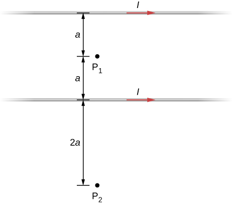
The accompanying figure shows ii long, straight, horizontal wires that are parallel and a distance 2a apart. If both wires behave current I in the aforementioned direction, (a) what is the magnetic field at [latex]{P}_{ane}?[/latex] (b) [latex]{P}_{ii}?[/latex]
Show Solution
At P1, the internet magnetic field is nada. At P2, [latex]B=\frac{3{\mu }_{o}I}{8\pi a}[/latex] into the page.
Repeat the calculations of the preceding problem with the direction of the current in the lower wire reversed.
Consider the expanse between the wires of the preceding problem. At what distance from the acme wire is the cyberspace magnetic field a minimum? Assume that the currents are equal and menses in reverse directions.
Show Solution
The magnetic field is at a minimum at distance a from the top wire, or half-mode between the wires.
Licenses and Attributions
Magnetic Field Due to a Sparse Straight Wire. Authored by: OpenStax College. Located at: https://openstax.org/books/university-physics-volume-2/pages/12-2-magnetic-field-due-to-a-thin-straight-wire. License: CC Past: Attribution. License Terms: Download for gratuitous at https://openstax.org/books/university-physics-volume-2/pages/one-introduction

Magnetic Field Of Straight Wire,
Source: https://pressbooks.online.ucf.edu/osuniversityphysics2/chapter/magnetic-field-due-to-a-thin-straight-wire/
Posted by: wolfkintil1963.blogspot.com
0 Response to "Magnetic Field Of Straight Wire"
Post a Comment